Precautions For Metal Pipeline Construction In Winter

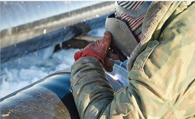
Metal pipeline construction points for attention in winter, the biggest characteristic of winter construction I think is that the temperature is relatively low, in the welding operation must pay attention to the temperature, the need to determine the temperature of the welding position before welding, in the case of lower than the process requirements of the temperature, the base metal must be preheated before welding. Attention should be paid to the thermal insulation problem after welding in winter. Attention should be paid to keep the materials dry in rain and snow. Measures should be taken during the welding construction in winter. If the temperature is above -5 degrees Celsius,  do some conventional drying and insulation. If the temperature is too low or the board is too thick, we need to preheat and pay attention to the insulation between layers.

Winter construction main technical measures

1. Pipe welding should be preheated in strict accordance with the requirements, and the pipe should be put into the closed workshop for heating in advance.

2. when the ambient temperature is below 5℃, it is not suitable for hydraulic test; The water of the pipeline that has been tested by hydraulic pressure should be drained out of the pipe in time and the pipe mouth should be temporarily blocked.

3. should try to avoid the pipeline pressure test in winter, if it must be in winter pressure test, to minimize the water filled pipeline exposure to the natural environment time, in line with the requirements of the specification under the premise, the test time should be as short as possible, after the test, to drain the water in the pipeline in time and maximize the blow dry.

4.The amount of prefabrication should be increased as much as possible to reduce the welding workload on site.

5. The wind speed during welding shall not exceed the following provisions; otherwise, windproof measures shall be taken:

A manual arc welding is 8m/s;

B hydrogen arc welding, carbon dioxide gas welding 2m/s

6.The relative humidity of the environment within 1m welding arc shall not be greater than 90%.

7. the welding environment temperature should be able to ensure that the welding parts required sufficient temperature and welder skills will not be affected.

8. Welding process requirements:

A When the ambient temperature is below 0℃, welding joints without preheating requirements, except austenitic stainless steel, should be preheated to more than 15℃ within 100mm of the initial welding site.

5 Nondestructive Testing Methods For Steel

The nondestructive testing of steel mainly involves ray testing, ultrasonic testing, magnetic particle testing, penetration testing and eddy current testing.

 1. Radiographic Detection (RT)
X-ray testing refers to the non-destructive testing method that uses X-ray or gamma ray to penetrate the specimen and uses film as the equipment for recording information. This method is the most basic and widely used non-destructive testing method.

2. Ultrasonic Detection (UT)
Ultrasonic testing is suitable for nondestructive testing of metal, nonmetal and composite materials. It can detect the internal defects of the specimen within a wide thickness range. For metal materials, can detect the thickness of 1 ~ 2mm thin wall pipe and plate, can also detect several meters long steel forgings; Moreover, the defect location is more accurate and the detection rate of area defects is higher. High sensitivity, can detect the internal size of the specimen is small defects; And the detection cost is low, the speed is fast, the equipment is light, harmless to the human body and the environment, the field use is more convenient.

3. Magnetic Particle Detection (MT)
Principle of magnetic particle detection is magnetized ferromagnetic material and workpiece, but because of the discontinuity, the magnetic field lines on the surface of the workpiece surface and near local distortion and a leakage magnetic field is generated, adsorption on the surface of the magnetic powder and magnetic marks visible form in the right light visual, showing the location, shape and size of discontinuity.

4. Penetration Testing (PT)
The principle of penetration detection is that after the surface of the part is coated with permeant containing fluorescent dye or colored dye, under the action of capillary, after a period of time, the permeable liquid can penetrate into the surface opening defects; After removing the surface excess penetrant, painted on the parts surface imaging agent again, also, under the action of capillary, imaging agent will attract defects in penetrants, penetrating fluid flow back into the imaging agent, in a certain light (uv light or white light), defect penetrant traces are reality, (yellow-green fluorescence or bright red), Thus, the morphology and distribution of defects are detected.

5. Eddy Current Testing (ET)
Eddy current testing places a coil with alternating current on a metal plate or outside a metal tube under test. At this time, an alternating magnetic field will be generated in and around the coil, resulting in a vortex-like induced alternating current in the specimen, called eddy current. The distribution and size of eddy current are not only related to the shape and size of the coil and the size and frequency of the AC current, but also depend on the conductivity, permeability, shape and size of the specimen, the distance from the coil and whether there are cracks on the surface.

API5L X52N X56Q PSL2 OD24″ Seamless pipeline

our factory have Φ720 rolling can produce big size seamless pipes directly . such as API5L X65QS PSL2 OD610*12.7mm by hot rolled producing Length 12m

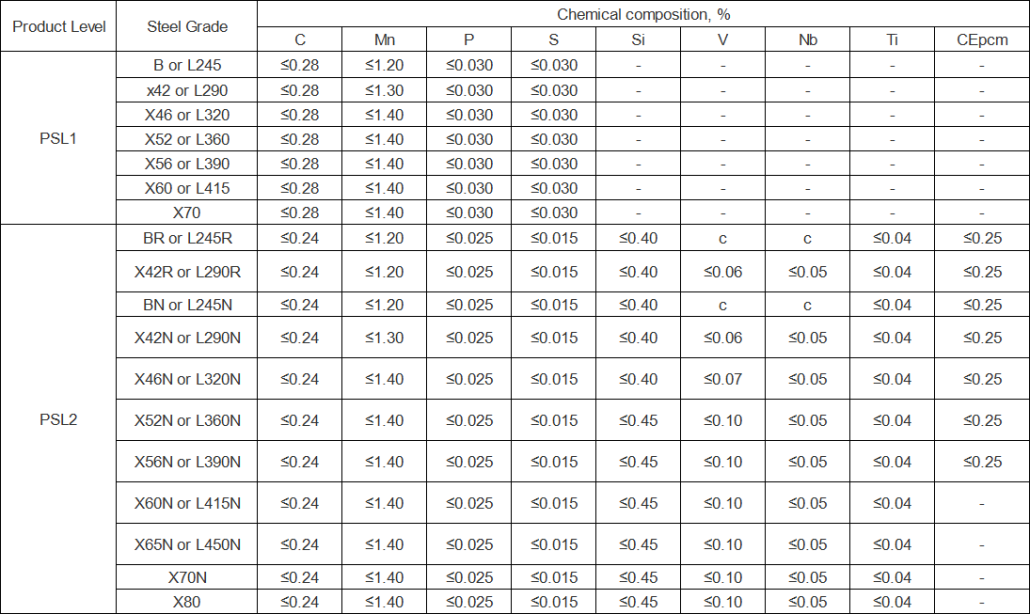
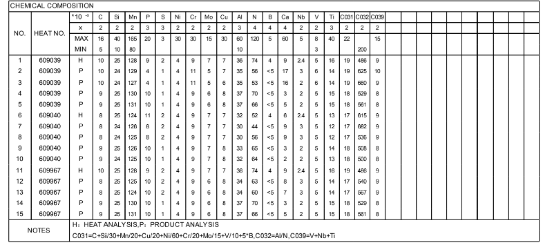
API5L X65QS PSL2 chemical composition:

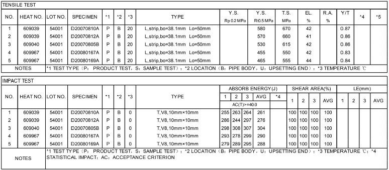
API5L X65QS PSL2 Mechanical Properties

www.wldsteel.com

[email protected]

Carbon steel material for Hydrogen sulfide corrosion applications

Hydrogen sulfide H₂S is an inorganic compound that is colorless, flammable, soluble in water acid gas, hydrogen sulfide corrosion refers to the oil and gas pipeline containing a certain concentration of hydrogen sulfide (H2S) and water corrosion.  H₂S dissolves in water and becomes acidic, leading to electrochemical corrosion and local pitting and perforation of pipelines. The hydrogen atoms generated in the corrosion process are absorbed by the steel and enriched in the metallurgical defects of the pipe, which may lead to the embrittlement of the steel and the initiation of cracks, leading to cracking. The pipeline and equipment of acid oil and gas fields containing H₂S have appeared many times sudden tearing or brittle fracture, welding zone cracking and other accidents, which are mainly caused by hydrogen-induced cracking (HIC) and sulfide stress cracking (SSC).

The factors affecting the corrosion of H₂S include hydrogen sulfide concentration, PH value, temperature, flow rate, carbon dioxide and chloride ion (C1-) concentration, etc. A wet hydrogen sulfide stress corrosion environment is constituted if the following conditions are met:

  • Medium temperature is not greater than 60+2P ℃, P is the medium gauge pressure (MPa);
  • B partial pressure of hydrogen sulfide is not less than 0.35mpa;
  • The medium contains water or the medium temperature is lower than the dew point temperature of water;
  • Medium with PH less than 9 or cyanide.

The results show that for the alloy steel when the strength or hardness of the steel is the same, the microstructure of uniform distribution of small spherical carbides can be obtained by high temperature tempering after quenching, and the resistance to H2S corrosion is better than that after tempering. The shape of inclusions also matters, especially the shape of MnS, because MnS are prone to plastic deformation at high temperatures, and the sheet MnS formed by hot rolling cannot be changed during subsequent heat treatment.

Elements Mn, Cr and Ni are added to the carbon steel to improve the hardenability, especially Ni. It is generally believed that Ni element is beneficial to the toughness of alloy steel, but the hydrogen evolution reaction overpotential of Ni steel is low, the hydrogen ion is easy to discharge and reduce to accelerate the hydrogen precipitation, so the resistance of Ni steel to sulfide stress corrosion is poor. In general, carbon steel and alloy steel should contain less than 1% or no nickel. Elements such as Mo, V, Nb, etc. that form stable carbides in steel.

ISO 15156-2, ISO15156-3 or NACE MR0175-2003 have limited the environmental conditions to avoid the occurrence of stress corrosion. If these conditions are not met, HIC and SSC tests shall be performed, and other relevant standards shall be met. The American Corrosion Institute (NACE) MR-01-95 states that to prevent sulfide stress corrosion cracking (SSCC), ordinary steel (nickel content less than 1%) with a hardness below Rockwell HRC22 or tempered chrome-molybdenum steel with nickel content less than HRC 26 shall be used.

In addition, there are other restrictions:

  • Impurities in steel: sulfur ≤ 0.002%, P≤0.008%, O≤ 0.002%.
  • Hardness is not more than 22HRC, yield strength is less than 355MP, tensile strength is less than 630MPa
  • The carbon content of steel should be reduced as much as possible under the condition of satisfying the mechanical properties of steel plate. For Low carbon steel and carbon-manganese steel: CE≤0.43, CE=C+Mn/6; For low alloy steel: CE≤045 CE=C+Mn/6+(Cr+Mo+V)/5+(Ni+Cu)/15

Steel plate:SA387 Gr11(HlC), SA387 Gr12(HlC), SA387 Gr22(HlC), SA516 Gr65(HlC), SA516 Gr70(HlC);

Steel pipe: API 5CT H40, J55, L55, C75(1,2,3), L80(type 1), N80(type Q/T), C95(type Q/T), P105, P110 Q/T); API 5L grade A, grade B, X42, X46, X52; ASTM A53, A106(A, B, C)

The avaiable carbon Steel pipe and plate for H₂S application

Welding of Ultra-supercritical boiler material

Heat-resistant steel refers to the steel that works at high temperature and has excellent thermal strength and thermal stability. Thermal strength refers to the ability to resist creep and fracture at high temperature, and thermal stability refers to the ability to resist oxidation and corrosion of gaseous media at high temperature. People usually refer to the heat-resistant steel with thermal strength as heat-resistant steel and heat-resistant steel with thermal stability as heat-stable steel. Heat-resistant steels are mainly used in power and energy engineering, such as in the manufacture of oil refining equipment, boilers, nuclear vessels, steam turbines, synthetic chemical vessels, aerospace equipment and other high-temperature processing equipment. It should be noted that many stainless steels (309, 310H) also have heat resistance and are sometimes referred to as “heat resistant stainless steel”.

The welded joints of heat resistant steel shall have substantially the same high temperature oxidation resistance as the base metal. The alloy composition and content of weld metal should be basically consistent with the base metal, such as Cr, Mo, W and other major elements, while impurities such as P and S should be controlled at a low level as far as possible to reduce the tendency of hot crack. In order to improve the weldability, the C content of the welding material can be slightly lower than that of the base metal to ensure the high temperature performance. The strength of the weld metal shall be similar to that of the base metal to be welded. Heat-resistant steel welded joints shall not only have short-term strength at room temperature and high temperature basically equal to that of the base metal, but also, more importantly, have high temperature creep properties similar to that of the base metal. The performance requirements of new heat-resistant steel joints for ultra-supercritical boilers are shown in the following table.

GradesT.S σb  MPaY.Sσs  MPaElongation δ%AkvJAllowable stress at operating temperature,MPaHardness, HB
P12263053017%3164 (620℃)225~270
P9263053017%3170(620℃)
HR3C6553069(650℃)
Super304H5903591(620℃)78(650℃)225~270

Although most of heat resistant steel welding structure is working under high temperature, but the final inspection for pressure vessels and piping requirements, usually at room temperature to 1.5 times the working pressure experiment hydraulic or pneumatic pressure test, the operation of pressure equipment or maintenance have to undergo the cold start process, so the heat resistant steel welding joint is also should have certain resistance to brittle fracture. For martensite and austenite heat resistant steels, the content of δ Ferrite in the deposited metal should be strictly controlled to ensure the creep property of the welded joints during the long time running at high temperature.

P92/T92, P122/T122 martensitic steel welding

Both P92 and P122 are martensitic steels, which have cold cracking tendency and hot cracking tendency during welding. In order to prevent cold cracks in welding, it is necessary to preheat before welding. The preheat temperature is not less than 150℃ for TIG welding and not less than 200℃ for electrode arc welding and submerged arc welding. In order to prevent hot crack and coarse grain, the welding line energy should be strictly controlled during the welding process, the interlayer temperature should be less than 300℃, and the tungsten electrode argon arc welding with small welding heat input is preferred. Multilayer and multi-pass welding should be paid attention to when welding electrode arc welding. The welding pass thickness should not be greater than the electrode diameter. The welding pass width should not be more than 3 times the electrode diameter and it is recommended that the electrode diameter should not be more than 4mm.For the workpiece with large wall thickness, submerged arc welding can be used for welding, but fine wire submerged arc welding should be used, and the diameter of the welding wire should be less than 3mm. When welding T122 and T92 small diameter tubes, the back side should be filled with argon during the whole welding process. For large-diameter thick-walled pipes, argon gas protection is required on the back of the first three layers of welds at the root. After weld welding, use asbestos insulation and slow cooling and stay between 100 ~ 150℃ for at least 1 ~ 2 hours, until the metallography is completely transformed into martensite, then can carry out post-weld heat treatment. For the wall thickness of the workpiece is greater than 40mm, after welding with asbestos insulation slow cooling, 100 ~ 150℃ at least stay 1 ~ 2 hours, if not immediately heat treatment, should be heated to 200 ~ 300℃ insulation 2 hours and then slow cooling to room temperature.

SUPER 304H, SA-213 TP310HCBN Austenitic steel welding

Austenitic steel has good weldability and no cold cracking tendency, so it does not need preheating. However, austenitic steel has hot cracking tendency during welding, so attention should be paid to the control of welding heat input and interlayer temperature. In the welding process, the welding method of welding line energy is smaller, such as manual TIG, automatic cold wire TIG welding or hot wire TIG welding. Generally, the interlayer temperature should be controlled not more than 150℃. For automatic cold wire TIG welding or hot wire TIG welding, the continuous welding process requires interlayer water cooling of the welded weld. In order to prevent intergranular corrosion, the chloride ion content in the cooling water should be controlled. In order to prevent the oxidation of alloying elements in the high temperature zone, the back surface should be filled with argon during the whole welding process. In order to ensure good fusion on both sides of groove, groove Angle of austenitic steel should be larger than that of general ferrite steel. For dissimilar steel welding with ferrite materials, ernicR-3 or EnICRFE-2 welding wire or electrode is recommended. When dissimilar steel is welded (with ferrite steel) and used at high temperatures, the expansion coefficient of both materials must be taken into account.


What is the creep-resistant steel used for?

Molybdenum has been a key alloying element in creep resistant ferrite steels operating at temperatures up to 530°C. The main applications of creep resistant steel are in power plants and petrochemical plants, where steam turbines require large forgings and castings, and pressure vessels, boilers and piping systems require tubes, plates and accessories of all kinds.In addition to high temperature creep strength, other material properties such as hardenability, corrosion resistance and weldability are also important. The relative importance of these properties depends on the specific application of the material. For example, large turbine rotors need steel with good hardenability, and power plant piping systems must be weldable. Even so, the alloys used in these different applications all use the same principles to improve creep strength.

Molybdenum in solid solution can reduce the creep rate of steel very effectively. When used at high temperatures, molybdenum slows the agglomeration and coarsening of carbides (ostwald’s ripening). Quenching and tempering produce a microstructure composed of upper bainite, resulting in the best results in high temperature strength. For coal-fired power plants, the efficiency of subcritical generating sets is less than 40 percent. Future ultra-supercritical (USC) plants are expected to be more than 50 percent efficient, reducing the carbon dioxide emissions per kilowatt-hour of electricity produced by almost half. Creep resistant ferrite steel is still commonly used in power plants, oil refineries and petrochemical plants worldwide. Components include seamless tubes for hot water boilers and superheaters, boiler drum, collector, pumps and pressure vessels for high temperature purposes, and steam turbine spines over 2 meters in diameter and over 100 tons in weight. This steel can be classified as C-Mn steel, Mo steel, low alloy C-RMO steel and 9-12% Cr steel.

Plant type Subcritical(Over 300000 kw)
Water wall :A192, SA-106B, SA-106C,
Overheating: T11/P12,P22/T22,T23, T91,T92
Reheater: P11,T23,T91,T92
Economizer: A192
Header and steam pipe: A192, T12, P12
Supercritical(SC)(Over 600000 kw)
Overheating: T22, T23, T91, T92, TP347H, TP347HFG, SUPER304H, HR3C
Reheater material: P12,T23,T91,T92,TP347H,TP347HFG,SUPER304H,HR3C
Economizer materials : A192, SA210C
Header and steam pipe: P11,P91, P92
Ultra-supercritical(USC)(Over 660000 kw)
Overheating material: T22,T23,T91,T92,TP347H,TP347HFG, SUPER304H, HR3C
Reheater: P12, T23, T91, T92, TP347H, TP347HFG, SUPER304H, HR3C
Economizer materials : A192, SA210C
Header and steam pipe: P11,P91,P92

How is the heat exchange tube connected with the tube sheet?

The connection form of heat exchange tube and tube plate mainly includes expansion, welding, expansion welding, etc. The strength expansion joint refers to the expansion of the sealing performance and tensile strength of the connection between the heat exchange tube and the tubesheet. It relies on the plastic deformation of the tube end to withstand the pulling force. The residual stress after the expansion of the tube will gradually weaken when the temperature increase so that the sealing performance and strength of the connection between the tube and the tube sheet will decrease. Therefore, the strength expansion is suitable for the design pressure is less than or equal to 4MPa, the design temperature is less than or equal to 300℃. The strength expansion should not be used in the case of severe vibration, large temperature difference, or obvious stress corrosion during operation.

When expanding the tube, the hardness of the tube should be lower than that of the tube sheet. The gap between the pipe and the pipe and the smoothness of the pipe affects the quality of the expanding pipe. The rough surface of the pipe hole can produce a large friction force and is not easy to pull off, but it is easy to produce leakage. The surface of the pipe hole is strictly prohibited to have a longitudinal through the groove. The smooth surface of the tube hole is not easy to leak, but easy to pull off. Generally, the surface roughness is required to be less than or equal to 12.5μm. There are two kinds of pipe holes: holes and annular grooving, the former as shown in figure (a) below, and the latter as shown in Figure (b) and (c) below.

After grooving, the steel tubes are squeezed into the grooves when expanding, which can improve the pull-off resistance and enhance the sealing performance. The number of annular slots in the tube hole depends on the thickness of the tube plate. Generally speaking, a slot is opened when the thickness is less than 25mm, and two slots are opened when the thickness is greater than 25mm. When the tube plate is thick or to avoid gap corrosion, the structure shown in the following figure (d) can be used, the composite tube plate and heat exchange tube can also be expanded, when the cladding is greater than or equal to 8mm, should be in the groove on the tube hole, the structure is shown in the following figure (e).

Strength welding refers to ensure the sealing performance and tensile strength of the heat exchange tube and tubesheet connection, is the most widely used tubesheet connection types. Strength welding manufacturing is simple, the tensile ability is strong, such as welding part failure, can be secondary repair welding, more convenient heat exchange tube. The use of strength welding is not limited by pressure and temperature, but it is not suitable for the occasion of large vibration or gap corrosion. The general form of strength welding is shown in figure (a) below. In order to avoid liquid accumulation around the pipe end, the structure as shown in figure (b) below is often used. The structure as shown in figure (c) below is generally used in the situation where the tubesheet is stainless steel.

The sealing performance of the joint between tube and tube plate is required to be high, or there is clearance corrosion, withstand severe vibration and other occasions, single expansion or welding can not meet the requirements, the combination of the two can provide enough strength and good sealing performance. The combination of expansion and welding can be divided into two kinds according to the expansion and welding sequence: expansion and welding after expansion. The general expansion method will inevitably have oil stains in the joint gap, which will be welded after expansion. These oil stains and the air in the gap will reduce the weld quality.

Weld before expansion, will cause damage to the weld. At present, there is no uniform provision for the choice of the two orders. In the actual engineering, such as expansion after welding, before welding should be clean oil; If the first welding after expansion, should be a limit to the expansion position of the tube end, generally to control from the surface of the tube plate 15mm above the scope of expansion. The first expansion and then welding generally adopts the form of strength expansion and seal welding. The strength expansion ensures the sealing performance of the tube and tubesheet, providing enough tensile strength, and the seal welding further ensures the sealing performance of the tube and tubesheet. The structure is shown in the figure (a). Strength welding ensures the sealing performance of the tube and tubesheet, providing sufficient tensile strength, and sticking expansion eliminate the gap between the tube and the tube hole to ensure the sealing performance. The structure is shown in figure (b).

In essence, explosive expansion is also a kind of strength expansion, the latter usually adopts roller expansion, the former uses the explosive in a very short period of time to produce high-pressure gas shock wave to make the pipe firmly attached to the tube hole. High explosive expansion and connection efficiency, no need of lubricating oil, easy to weld after expansion, large tensile strength, small axial elongation and deformation.

Explosive expansion is suitable for thin wall tubes, small diameter tubes and large thickness tube sheet expansion, heat exchange tube end leakage, mechanical expansion is difficult to repair the occasion.

How do alloying elements affect the performance of cryogenic steels?

We usually call the steel used the temperature range -10 to -273℃ as low-temperature steel or cryogenic steel According to alloying element content and structure, cryogenic steels can be divided into: Aluminum killed C-Mn steel such as 06MnVTi, 06MnVal, 09Mn2Vre, 06MnNb steel, low alloy ferric body low-temperature steel 0.5Ni, 2.5Ni, 3Ni, 3.5Ni, etc., Martensiform low-temperature steels such as 9Ni, 5Ni steel, high alloy austenitic low-temperature steels such as 1Cr18Ni9Ti and 20Mn23Al and so on.

The effect of alloying elements in low-temperature steels mainly refers to its effect on the low-temperature toughness of steels:

C

With the increase of carbon content, the brittle transition temperature of steel increases quickly and the welding property decreases, so the carbon content of low-temperature steel is limited to less than 0.2%.

Mn

Manganese can improve obviously the low-temperature toughness of steel. Manganese mainly exists in the form of solid solution in steel and plays the role of solid solution strengthening. In addition, manganese is an element that enlarges the austenite region and reduces the transformation temperature (A1 and A3). It is easy to obtain fine and ductile ferrite and pearlite grains, which can increase the maximum impact energy and significantly reduce the brittle transition temperature. In general, the Mn/C ratio should be equal to 3, which can not only reduce the brittle transition temperature of steel, but also compensate for the decrease of mechanical properties caused by the decrease of carbon content due to the increase of Mn content.

Ni

Nickel can alleviate the tendency of brittle transition and significantly reduce the temperature of brittle transition. The effect of nickel on improving the low-temperature toughness of steel is 5 times that of manganese, that is, the brittle transition temperature decreases by 10℃ with the increase of nickel content by 1%. This is mainly because of nickel with carbon, absorbed by the solid solution and reinforcement, nickel also makes a move to the left point of eutectoid steel eutectoid point to reduce the carbon content, reduce the phase transition temperature (A1 and A2), in comparison with the same carbon content of carbon steel, decrease in the number of ferrite and refining, pearlite populations (the carbon content of pearlite is also lower than carbon steel). The experimental results show that the main reason why nickel increases the toughness at low temperature is that nickel-containing steel has more movable dislocations at low temperature and is easier to cross slip. For example, medium alloy low carbon martensiform low-temperature steel 9Ni steel, has high low-temperature toughness, can be used for -196℃. The 5Ni steel developed on the basis of 9Ni steel has good low-temperature toughness at -162~-196℃.

P, S, Sn, Pb Sb

Phosphorus, sulfur, arsenic, tin, lead, antimony: these elements are not conducive to the low-temperature toughness of steel.

They segregate in the grain boundary, which reduces the surface energy and resistance of the grain boundary, and causes the brittle crack to originate from the grain boundary and extend along the grain boundary until the fracture is complete.

Phosphorus can improve the strength of steel, but it will increase the brittleness of steel, especially at low temperatures. The brittle transition temperature is obviously increased, so its content should be strictly limited.

O, H, N

These elements will increase the brittle transition temperature of steel. Deoxidized silicon and aluminum killed steels can improve the toughness at low temperatures, but because silicon increases the brittle transition temperature of steels, aluminum killed steels have a lower brittle transition temperature than silicon killed steels.

The weldability of J55 oil casing

The oil casing is composed of a collar and pipe body. A single pipe body is connected with the collar thread and transported to the oil field site with end to end connection to facilitate transportation and use after reaching the required length. In order to strengthen the strength and anti-loosening control of the threaded connection, it is necessary to weld the coupling with the pipe body after the threaded connection, so it is very important to analyze the welding performance and formulate a reasonable welding process. API 5A J55 is one of the most commonly used casing materials, and we analyzed its weldability in terms of its carbon equivalent.

API 5CT J55 Chemical Composition

GradeCSiMnPSCrNiCuMo
API 5CT J550.34-0.390.20-0.351.25-1.500.0200.0150.150.200.20/

According to the carbon equivalent formula of the International Institute of Welding:

CE=C+Mn/6+(Cr+Mo+V)/5+(Ni+Cu)/15

CE=0.69>0.4

Its carbon equivalent is more than 0.4 and its weldability is poor. In order to obtain qualified welding quality, high preheating temperature and strict technological measures are needed.

Its weldability was analyzed according to the influence of J55 alloy element content on microstructure and properties:

  • J55 casing tube has a high carbon content, that’s 0.34%~0.39%, which makes the supercooled austenite transition curve of steel move to the right and increase; The addition of Cr, Mn, Ni, Cu and other alloy elements makes the transition curve of supercooled austenite shift to the right, which enhances the stability of the supercooled austenite, and increases the MS point (the beginning point of martensite formation). All these effects increase the quenching tendency of J55, and welding cracks have appeared.
  • J55 has a large tendency to cold crack, mainly quenching and embrittlement crack. Due to its high strength, high maximum hardness value of welding heat affected zone and rapid cooling, martensite is easily generated. When welding, try to choose large line energy and welding current, should not excessively reduce the welding speed. In order to reduce the cooling rate, extend the cooling time of the welded joint from 800 ℃ to 500℃, improve the microstructure of the weld metal and the heat-affected zone, and reduce the maximum hardness of the heat-affected zone, preheating before welding and tempering after welding is required.
  • The hot crack tendency of J55 is not high because its thermal conductivity is not easy to generate low fusion eutectic; The reheat crack tendency is not large, because it does not contain strong carbide. The welding wire ER55-G matched with its strength is selected. The welding wire has excellent welding process performance, high Ni content, strong cold crack resistance, and excellent comprehensive mechanical properties of the deposited metal.
  • Due to the large heat input required for J55 welding, the strength value of base material and welding material is large, and the internal stress during welding is extremely large. During welding, it is necessary to hammer the weld while welding. After welding, heat treatment is carried out to eliminate the internal stress and avoid the post-welding cracking caused by excessive stress. Post-weld heat treatment can also improve the welding microstructure properties.

Welding process of J55

Welding method 1: 80% Ar+20%CO2 gas shielded welding. Welding material: welding wire ER55-G, diameter Φ3.2mm. Welding parameters: current 250~320A, voltage 26 ~30V; Welding speed 35~50cm/min;

The preheating temperature is 100℃, and the interlayer temperature is not lower than the preheating temperature, but it is not allowed to be higher than the preheating temperature of 30℃.

Post-welding treatment: air cooling without any heat treatment.

Results: The tensile test was qualified. The impact values of the three samples in the heat-affected zone are 26,47,23, unqualified. The four side bending samples have 3.75mm crack, 4mm crack, 1.38mm crack, 0.89mm crack, respectively, which are unqualified. This technological scheme is not reasonable.

Welding method 2: 80%Ar+20%CO2 gas welding. Welding material: welding wire ER55-G, diameter Φ3.2mm. Welding parameters: current 250~320A, voltage 26 ~30V; Welding speed 35~50cm/min; The preheating temperature is 100℃, and the interlayer temperature is not lower than the preheating temperature, but it is not allowed to be higher than the preheating temperature of 30℃.

Post-welding treatment: tempering treatment, temperature 600±20℃, holding time for 4h; Heating rate 50℃/h, cooling rate 50℃/h.

Results: The tensile test was qualified. The impact values of the three samples in the heat-affected zone are 51, 40 and 40, respectively, which are qualified.

Side bending test, qualified; The experiment proves that this technological scheme is reasonable. Post-welding heat treatment can improve the welding microstructure and properties, which is one of the important factors for J55 welding to obtain the welded joints that meet the technical requirements.

The harsh API 5A J55 casing environment requires the quality of the pipe itself, also the quality of the welding. Through the above welding analysis and test, the welding process that can meet the requirements is obtained, which provides a theoretical and experimental basis for the correct welding of oil casing.

Advantages of U tube heat exchanger

U tube heat exchanger is characterized by its simple structure, good tightness, convenient maintenance and cleaning, low cost, good thermal compensation performance and strong pressure bearing capacity. The U-tube heat exchanger has the largest heat exchange area under the same diameter. The main structure of U-shaped tube heat exchanger includes tube box, cylinder, head, heat exchange tube, nozzles, baffle, anti-shock plate and guide tube, anti-short circuit structure, support and other accessories of the shell and tube side, is the most commonly used in shell and tube heat exchanger.

Heat exchange tube

Heat exchange tubes used for heat transfer usually use primary cold-drawn heat exchange tubes and ordinary cold-drawn heat exchange tubes. The former is suitable for heat transfer and vibration occasions without phase change, and the latter is suitable for reboiling, condensing heat transfer and vibration-free general occasions. The heat exchanger pipe shall be able to withstand certain temperature differences, stress and corrosion resistance. The length of the heat exchange tube is generally 1.0m, 1.5m, 2.0m, 2.5m, 3.0m, 4.5m, 6.0m, 7.5m, 9.0m, 12.0m. The material of the pipe can be carbon steel, stainless steel, aluminum, copper, brass and copper-nickel alloy, nickel, graphite, glass and other special materials, also often used composite pipe. In order to expand the area of effective heat transfer tube at the same time maximize the tube side heat transfer coefficient, heat exchange tube processing or in tube inserted into the internal and external surfaces of the disturbed flow components, producing fluid turbulence the inside and outside at the same time, commonly used such as rough surface tubes, finned tube, the supporting pipe, inside the plug-in type, etc.

Tube sheet

Tube sheet is one of the most important parts of shell – tube heat exchanger. The tube plate is the barrier between the shell side and the pipe side. When the heat exchange medium has no corrosion or slight corrosion, it is generally made of low carbon steel, low alloy steel or stainless steel. The connection form of tube-sheet and shell is divided into non-detachable and detachable types. The former is the connection between tube-sheet and shell in the fixed tube-sheet heat exchanger. The latter, such as U-shaped tube type, floating head type and stuffing box type and sliding tube plate type heat exchanger tube plate and shell connection. For removable connections, the tube plate itself is usually not in direct contact with the shell, but the flange is connected to the shell indirectly or is clamped by two flanges on the shell and the tube box.

Tube box

Most of the shell tube heat exchangers with larger shell diameters adopt tube and box structures. The tube box is located at both ends of the heat exchanger, which evenly distributes the fluid from the pipe to the heat exchanger tubes and gathers the fluid in the tubes together to send out the heat exchanger. In a multi-pipe shell, the casing can also change the flow direction. The structure of the tube box is mainly determined by whether the heat exchanger needs to be cleaned or whether the tube bundle needs to be divided.

Shell and U-tube heat exchanger has become the most commonly used structure type of heat exchanger in the field of petrochemical industry due to many advantages, but it also has some disadvantages such as pipe cleaning is more difficult, the utilization rate of tube plate is low due to the limitation of curvature radius of bend pipe; The distance between the innermost tubes of the tube bundle is large, the shell process is easy to short circuit, and the scrap rate is high. It is suitable for large temperature difference between pipe and shell wall or shell side where medium is easy to scale and needs cleaning, and is not suitable for using floating and fixed tube plate type occasions, especially suitable for clean and not easy to scale under high temperature, high pressure, corrosive medium.